Thursday, 5 April 2012
Thursday, 29 March 2012


Monday, 26 March 2012


CIVIL ENGINEERING STUDENTS SEMINAR PHOTOSHOOTS
KLR COLLEGE OF ENGINEERING & TECHNOLOGY
CIVIL ENGINEERING DEPARTMENT LOGO & WEBSITE INAUGURATED
BY
Shri.Er.S.R.RAMA MURTHY
B.E,C.E,FIE,FIV,FICA
ON 26th MARCH 2012


Department of Civil Engineering

| Introduction There is no one typical career path for civil engineers. Most engineering graduates start with jobs of low responsibility, and as they prove their competence, they are given more and more responsible tasks, but within each subfield of civil engineering, and even within different segments of the market within each branch, the details of a career path can vary. In some fields and firms, entry-level engineers are put to work primarily monitoring construction in the field, serving as the "eyes and ears" of more senior design engineers; while in other areas, entry-level engineers end up performing the more routine tasks of analysis or design and interpretation. More senior engineers can move into doing more complex analysis or design work, or management of more complex design projects, or management of other engineers, or into specialized consulting. | ||||||||||||||||||||||||||||||||||||
| ||||||||||||||||||||||||||||||||||||
KLR COLLEGE OF ENGINEERING & TECHNOLOGY
KLR COLLEGE OF ENGINEERING & TECHNOLOGY:
KLR College of Engineering & Technology (KLRT for short) is affiliated to the JNTU Hyderabad. It is located about 3 kilometers away from the Paloncha – the commuting time to KLRT being an 5 min from Paloncha & 30 min from Kothagudem, KLRT buses plying from various parts of the Paloncha & Kothagudem to the campus at BCM Road, Paloncha, Khammam Dist, The drive is across an exquisite expanse of green cover that transports one into a veritable echelon of contentment and heightened expectations.
The journey culminates with a panoramic view of what is talked about today as the ‘most happening place’ among educational institutions which sprawls across 20 acres of land. KLRT is part of the KLR INSTITUTIONS that has in its ambit as many as 37 educational institutions at Paloncha & Kothagudem Khammam Dist & Rajamandry E.Godavari District.
Thanks to the vision of our Founder Chairman, Late Dr. K.Laxma Reddy Garu who was committed to providing access to higher education for the rural regions of A.P. He was not only an altruist but also an educationalist and a visionary with extraordinary acumen & focused on catalyzing the holistic development of the student so that the latter takes his or her rightful place in Society. KLRT offers 7 courses in Engineering at the undergraduate level and MBA. In order to meet the increasing demand for quality education offered by KLRT, KLRT has hostel facilities for close to 150 boys and girls. The hostel facilities are being augmented perpetually aimed at the harmonious development of a student’s faculties. Efforts are on to make the campus fully residential in the next couple of years.
Mission/ Objectives
KLRT'S Vision
To be a premier Institute in the country and region for the study of Engineering and Management by maintaining high academic standards which promotes the analytical thinking and independent judgment among the prime stakeholders, enabling them to function responsibly in the globalized society.
KLRT'S Mission
To be a world-class technology Institute, achieving excellence in research and consultancy in cutting-edge technologies and be in the service of society in promoting continued ethical education in engineering and management.
| KLRT'S Goals | ||
| 01 | : | To be an Autonomous Institution |
| 02 | : | To be a Nationally & Internationally acclaimed institute for Research and Development |
| 03 | : | To be an Incubation institute for Techno-Managerial Enterprises. |
| 04 | : | A fully supportive Institute to Backward & Rural area students, and either scholarship wise, career development wise, placements, higher education. |
| 05 | : | To be recognized internationally as a Research and Development Centre by forging collaborations with research bodies, government entities, industries. |

Suspension bridge
A suspension bridge is one of the types of bridges in which the Deck(the load bearing portion) is hung below suspension cables on vertical suspenders.
The cables (or ropes or chains) are strung across the river through two tall towers.
Suspension bridges are aesthetic, light, and strong.
Suspension bridges can span distances from 2,000 to 7,000 feet—far longer than any other kind of bridge.
True to its name, a suspension bridge suspends the roadway from huge main cables, which extend from one end of the bridge to the other.
Suspension bridges built over waterways, can be built high, allowing the passage of tall ships unhindered by the bridge.
During construction, temporary central supports do not need to be built, and access to the construction is not required from beneath.
This means busy roadways and waterways do not need to be disrupted.
The added flexibility of suspension bridges allows them to flex under the power of winds and earthquakes
They tend to be the most expensive to build.
Suspension bridges can be unstable in extremely turbulent conditions, with extreme cases requiring temporary closure of the bridge.
When built in soft ground, suspension bridges require extensive and expensive foundation work to combat the effects of the heavy load on foundation towers.
Flexibility can be a disadvantage to suspension bridges, which can flex under heavy, concentrated loads. Suspension bridges are not generally used for regional rail crossings that carry maximum weight loads, causing added stress on the bridge.
The main Parts of a
Suspension Bridge are
Deck
Suspension cable
Suspender
Tower
Floor beams
Backstay
Anchorage Block ( Dead man )
Approach ramp
Suspension bridge has cables suspended between towers.
The towers enable the main cables to be draped over long distances.
The main cables continue beyond the pillars to deck-level supports, and further continue to connections with anchors in the ground.
Most of the weight of the bridge is carried by the cables to the anchorages, which are imbedded in massive concrete blocks.
The suspension cables must be anchored at each end of the bridge, since any load applied to the bridge is transformed into a tension in these main cables.
Inside the anchorages, the cables are spread over a large area to evenly distribute the load and to prevent the cables from breaking free.
The vertically suspended cables are known as suspenders.
Vertical suspended cables carry the weight of the deck below, upon which traffic crosses.
The roadway is supported by vertical suspender cables or rods, called hangers.
The main suspension cable in the early nineteenth century was often made from chain or linked bars, but modern bridge cables are made from multiple strands of wire.
The reason is that as spans increased, engineers were unable to lift larger chains into position, whereas wire strand cables can be largely prepared in mid-air from a temporary walkway.
The cables are made of individual steel wires bound tightly together, which is very strong under tension, is an ideal material for cables. A single steel wire, only 0.1 inch thick, can support over half a ton without breaking.
Suspension bridges have caused disasters in the past because of these cables.
As said that in early stages suspension bridges were made using chain links of heavy steel for the main cable.
If only one chain link failed, the whole bridge would collapse, as what happened to the Silver Bridge in 1967, killing 46 people.
Because of these reasons, suspension bridges use bundles of cables in recent time as said earlier. If one or two of the cables fails, the bridge still stays intact.
Three kinds of forces operate on any bridge: the dead load, the live load, and the dynamic load.
Dead load refers to the weight of the bridge itself.
Live load refers to traffic that moves across the bridge.
Dynamic load refers to environmental factors such as sudden gusts of wind and earthquakes
The main forces in a suspension bridge of any type are tension in the cables and compression in the pillars.
The force of compression pushes down on the suspension bridge's deck, but because it is a suspended roadway, the cables transfer the compression to the towers, which dissipate the compression directly into the earth where they are firmly entrenched.
The supporting cables, running between the two anchorages, are the lucky recipients of the tension forces.
The anchorages are also under tension, but since they are held firmly to the earth, the tension they experience is dissipated.
Since almost all the force on the pillars is vertically downwards and they are also stabilized by the main cables, the pillars can be made quite slender.
The weight is transferred by the cables to the towers, which in turn transfer the weight to the ground.
The following opposing forces act on the deck & the suspension cable:
one downward force caused by the load of the roadway.
one force in one part of the cable, pulling up and to the left.
one force in the other part of the cable, pulling up and to the right.
In the modern world, the longest suspension bridge is Japan's Akashi Kaikyo Bridge, which spans 6,432 feet.
Today, wind tunnel testing of bridge designs is mandatory. Lake of this disaster may occur.
So with these specifications we can conclude that in some special conditions Suspension bridges are more reliable than any other.
A.SURYA PRAVEEN

NAME : A.SURYA PRAVEEN
REGD.NO : 08QT1A0143
BATCH : 2008-2012
MOB NO : 9959609197
E-MAIL : suryapraveen_a@yahoo.com
MD.NASER AHMED

NAME : MD.NASER AHMED
REGD NO : 08QT1A0108
BATCH : 2008-2012
MOB NO : 9177918063
E-MAIL : naser.ahmed01@gmail.com


Green House Buildings
Green building is the
practice of creating structures
which are environmentally
responsible and
resource-efficient throughout
a building's life.
Green building can also be termed as
Sustainable building or Green architecture.
or factory in the world is still a kind of
steamship, polluting, contaminating, and
depleting the surrounding environment,
and relying on scarce amounts of natural
light and fresh air. People are essentially
working in the dark, and they are often
breathing unhealthful air.
P
O
L
L
U
T
I
O
N
buildings, we can use Green buildings.
Imagine, a building as a kind of tree. It would
purify air, accrue solar income, produce more
energy than it consumes, create shade and
habitat, enrich soil, and change with the seasons.
A building consumes:
natural resources.
Ø 1/4 of all virgin wood
harvested (not including
furniture).
Green buildings are
designed to reduce the
overall impact of the built
environment on human
health and the natural
environment.
Common Objectives
Protecting occupant health and improving employee productivity.
Efficiently using energy, water, and other resources.
Reducing waste, pollution and environmental degradation.
Green buildings with LEED Certification
meet high environmental standards.
Although a building may be designed efficiently, the systems and equipment must be maintained and continually monitored to retain the high level of efficiency.
Reuse and recycling is important to get the most out of our resources and to maintain a sustainable relationship between economics and our environment.
Use green buildings
practice of creating structures
which are environmentally
responsible and
resource-efficient throughout
a building's life.
Green building can also be termed as
Sustainable building or Green architecture.
Today even the most advanced building
or factory in the world is still a kind of
steamship, polluting, contaminating, and
depleting the surrounding environment,
and relying on scarce amounts of natural
light and fresh air. People are essentially
working in the dark, and they are often
breathing unhealthful air.
P
O
L
L
U
T
I
O
N
Instead of using these congested & polluted
buildings, we can use Green buildings.
Imagine, a building as a kind of tree. It would
purify air, accrue solar income, produce more
energy than it consumes, create shade and
habitat, enrich soil, and change with the seasons.
A building consumes:
| Ø | 2/5 of world energy | |
| Ø | production. 1/6 of all water pumped | out |
natural resources.
Ø 1/4 of all virgin wood
harvested (not including
furniture).
Green buildings are
designed to reduce the
overall impact of the built
environment on human
health and the natural
environment.
Common Objectives
Protecting occupant health and improving employee productivity.
Efficiently using energy, water, and other resources.
Reducing waste, pollution and environmental degradation.
Green buildings with LEED Certification
meet high environmental standards.
Although a building may be designed efficiently, the systems and equipment must be maintained and continually monitored to retain the high level of efficiency.
Reuse and recycling is important to get the most out of our resources and to maintain a sustainable relationship between economics and our environment.
Use green buildings
NAM ROAD PROJECT
1. Expansion of highways from 2 lanes – 4 lanes
Highways: National Highways are the main highways running through the length and breadth of the Indian union, connecting ports , foreign highways and capitals of states and including roads of strategic and military value. They constitute the frame on the which entire road communication system of the Country is based.
Types of Highways:
1)National Highways: National Highways are the main highways running through the length and breadth of the Indian union
2)State High ways: State High ways are the other maintain trunk are arterial roads of a state, connecting up with national head quarters and important cities within the state.
3)District Roads: District Roads are the roads traversing each district of the serving area of production and markets and connecting this with each other are with national and state highways or railway or important navigational routes.
4)Village Roads: Village Roads are roads connecting villages of groups of villages with each other.
In India in most of the Metro politan cities and in other cities roads are two way lanes by which traffic problems are High.Number of vehicles are increasing day by day, two way lanes are not having space for all the vehicles.Govt. is trying to expand the the two way lanes to four way lanes.
In india vehicle has to travel in left side only.Roads are divided into columns as Twoway lanes and four way lanes.Road dividers divides the Lanes into parts as per the Road
Two way lanes are the roads in which road is divided into two columns . only one heavy vehicle can go in one column of the road. Third heavy vehicle cannot fit properly in the two way lanes.
Fig.No.1.1
Four way lanes are the roads in which road is divided into Four columns. Left side of divider having two columns in which two heavy vehicles can go in same direction same with right side of the divider.only two heavy vehicle can go in one column of the road.
To reduce the traffic and for the convenience, Govt. is expanding the roads and highways as two way lanes into four way lanes.
For the transportation of vehicles national Highways now expanding as four way lanes.
Extension of Two way lanes to Four way lanes.
The design and construction of the road in embankment and in cuttings shall be carried out in accordance with Section 300 of MORTH Specifications and the requirements, and standards and specifications given in this Section. This Section also covers specifications for subgrade and earthen shoulders.
Efforts should be made to remove the inherent deficiencies in plan and profile of the existing road. The final centre line of the road and the road levels shall be fixed duly considering all the relevant factors covering structural soundness, safety and functional requirements as per relevant IRC Codes and provisions of this Manual.
The existing road embankment shall be widened/ modified to the specified cross-sectional details.
Materials
Materials and Physical Requirements: All materials to be used in works shall be in conformity with the requirements laid
down for relevant item in IRC/MORTH Specifications unless otherwise specified
in this Section. If the Concessionaire proposes to use any material, which is not
covered in IRC/MORTH Specifications, it shall conform to relevant Indian
Standards, if there are any, or to the International Standards. Proprietary products
proposed to be used shall be proven by use in comparable international road and
bridge projects, and shall be supported with authenticated licensing arrangement
with the manufacturer.
The Concessionaire shall identify the proposed sources of materials and submit
the proposal prior to delivery. If it is found that proposed sources of supply do not
produce uniform and satisfactory products at any time during execution, the
Concessionaire shall procure acceptable materials conforming to the specifications
from other sources.
Structural Concrete: The Concrete for use in structures shall conform to the provisions in Clauses 302.6 to 302.9 of IRC:21 and Section 1700 of MORTH Specifications. Wherever High Performance Concrete (HPC) is proposed to be used, the same shall conform to the provisions of IRC:SP:70. Sampling and testing of concrete shall be as per Clause 302.10 of IRC:21.
Acceptance criteria for concrete shall conform to Clause 302.11 of IRC:21.
Cement
Any type of cement specified in IRC:21 may be used for the works subject to limitations,if any, specified therein.
Coarse Aggregates
Before commencement of the works, at least three samples, in accordance with the procedure laid down in IS:2430, shall be taken for each quarry source to ascertain the quality, suitability and fitness of the available material for use in the works. Fresh tests shall be conducted in case there is any change in the source or the type of rock being quarried. The proposal, along with a copy of test reports, shall be submitted
Sand/Fine Aggregates
(i) All fine aggregates shall conform to IS:383 and tests for conformity shall be carried out as per IS:2386 (Part I to VIII). The fineness modulus of fine aggregates shall be between 2.0 and 3.5.
(ii) Before the commencement of the works, at least three samples as per IS:2430 shall be taken for each quarry source to ascertain the quality, suitability and fitness of the available material for use in the works and the proposal along with a copy of test reports shall be submitted to the IE for review and comments, if any.
(iii) Fine aggregates having positive alkali-silica reaction shall not be used.
Water
(i) Water for use in the works for mixing and curing of concrete shall be in conformity with Clause 302.4 of IRC:21.
(ii) Water from each source shall be tested before the start of works and thereafter
every three months and after each monsoon till the completion of the works andthe proposal along with a copy of test reports shall be submitted to the IE for
review and comments, if any.
Chemical Admixtures
The following guidelines shall apply in selection and use of admixtures:
(i) Chemical admixtures shall comply with IS:9103 and meet the requirements
stipulated in clause 5.5 of IS:456.
(ii) Admixtures generating hydrogen or nitrogen or containing nitrates, sulphides, sulphates, or any other material liable to affect the reinforcement/embedments or concrete shall not be used.
(iii) Compatibility of admixture with the cement being used shall be tested before actual use in the works. The test shall be repeated in case of change of type or grade or source of cement.
Steel
Steel for Prestressing
In addition to the requirement mentioned in Clause 1009.2 of MORTH Specifications, the steel for prestressing shall satisfy following conditions:
Uncoated stress relieved low relaxation steel conforming to IS:14268.
(ii) Prestressing steel shall be subjected to acceptance tests in respect of modulus of elasticity, relaxation loss at 1000 hrs, minimum ultimate tensile strength, stressstrain curve etc. prior to actual use on works as per guidelines contained in BS:4447. The modulus of elasticity value, as per acceptance tests, shall conform to the design value, which shall be within a range not more than 5 per cent between the maximum and the minimum.
Bitumen
Bitumen shall be paving bitumen of viscosity grade complying with Indian Standard Specifications for “Paving bitumen” IS:73:2006 of grade appropriate for the traffic and climatic conditions of the Project Highway. The heavily trafficked roads in hot areas may find harder grade bitumen more appropriate while pavements in mountainous regions subject to sub-zero temperatures during winter months carrying relatively lower traffic loads and subject to the phenomenon of “Frost Heave” may find less viscous bitumen resistant to fatigue and cold cracking more appropriate.
The material to be used in sub grade shall satisfy the design California Bearing Ratio (CBR) at the specified density and moisture content.. Taking into account slope stability, bearing capacity, consolidation, settlement and safety considerations based on geotechnical and investigation data. Where the embankment is to be supported on a weak stratum, appropriate remedial/ground improvement measures shall be taken.
Side slopes shall not be steeper than 2H:1V unless soil is retained by suitable soil retaining structures. The side slopes shall be protected against erosion by providing a suitable vegetative cover, kerb channel, chute, stone/cement concrete block pitching or any other suitable protection measures depending on the height of the embankment and susceptibility of soil to erosion. Drainage arrangement shall be provided as per Section 6 of this Manual.
Soil investigations and tests in accordance with the requirements specified in IRC:
SP:19 and shall be reported in the Proforma given in Table 1 of IRC:SP:19. In
addition to this, all tests as per the requirements of MORTH Specifications shall
be reported.
To assess the likely compresive strength of concrete by using rebound hammer as per IS: 13311 (Part 2) - 1992.The rebound of an elastic mass depends on the hardness of the surface against which its mass strikes. When the plunger of the
rebound hammer is pressed against the surface of the concrete, the spring-controlled mass rebounds and the extent of such a rebound depends upon the surface hardness of the concrete. The surface hardness and therefore the rebound is taken to be related to the compressive strength of the concrete. The rebound value is read from a graduated scale and is designated as the
rebound number or rebound index. The compressive strength can be read directly from the graph provided on the body of the hammer.
Along the alignment of the road, where unstable strata, soft material or poor subsoil conditions have been met with at the foundation level, the soil profile shall be drawn after determining through borings, the type of soil at different levels. The borings shall be at maximum interval of 100 m to a depth of 2 m or more below the existing ground as necessary. In the case of high embankments, the borings shall be taken down to a depth equal to twice the height of the embankment.
(f) Any particular construction problems of the area or other important features.
(g) Geotechnical properties of pond ash, covering parameters specified in Table 1 of IRC: SP: 58 and Optimum Moisture Content (OMC) – dry density relationship for heavy compaction. This information shall be furnished, in case pond ash is used in embankment construction.
Designing
GEOMETRIC DESIGN AND GENERAL FEATURES
General
(i) This section lays down the standards for geometric design and general features for four-lane divided carriageway.
(ii) (a) In built-up areas, 6-lane divided carriageway along with service roads shall be provided as part of 4-laning of the Project Highway. Such stretches where the requirement of 6-laning is dispensed with and only 4-laning with or
without service road and footpath is to be provided will be as indicated in
Schedule-B of the Concession Agreement.
(b) Where there is constraint of ROW width, the Authority may specify
construction of a bypass. The alignment of the bypasses shall be as specified
in Schedule-B and in conformity with the site earmarked in Schedule-A of
the Concession Agreement.
(iii) The geometric design of the Project Highway shall conform to the standards set out in this section as a minimum.
(iv) As far as possible, uniformity of design standards shall be maintained throughout the length of the Project Highway. In case of any change, it shall be effected in a gradual manner.
(v) Where the existing road geometrics are deficient with respect to minimum
requirements and its improvements to the prescribed standards is not feasible due to any constraint in acquisition of additional land, such stretches shall be as specified
in Schedule-B of the Concession Agreement.
(vi) Existing horizontal curves, which are found deficient in radius, layout, transition lengths or super-elevation shall be corrected to the standards specified in this section.
(vii) Any deficiencies in the vertical profile in respect of grades, layout of vertical curves and sight distance shall be corrected to meet the minimum requirements specified in this section.
Pavement Design
The design and construction of new pavement sections, and of strengthening measures(overlay) for the existing pavement shall be carried out in accordance with the criteria,standards and specifications given in this section. Where alternative specifications or materials are proposed to bring in innovation in design etc The design of new pavement sections or strengthening of existing pavements shall take into account all relevant factors for assuring reliable performance and shall also satisfy the specified minimum performance requirements.
The Concessionaire shall undertake the necessary soil, material and pavement
investigations and traffic volume and axle load studies in accordance with the good industry practice for preparing detailed designs.
The materials, mixes and construction practice shall meet the requirements prescribed in the MORTH/IRC Specifications.
Where problematic conditions such as expansive soils, swamps or marshes, flooding,poor drainage, frost susceptible areas etc. are found to exist, adequate measures shall be adopted to deal with such site conditions.
Design Traffic
The design traffic shall be estimated in terms of cumulative number of standard axles(8160 kg) to be carried by the pavement during the design period. Estimate of the initial daily average traffic flow shall be based on at least 7 days, 24 hrclassified traffic counts. IRC: 9 may be used as guidance for carrying out the traffic census. Any likely change in traffic due to proposed four laning of the facility and/or futuredevelopment plans, land use, shall be duly considered in estimating the design traffic.
Traffic growth rate shall be established for each category of commercial vehicles to be considered for design of pavement. For traffic projections, the procedure outlined in IRC: 108 may be followed. The Concessionaire shall adopt a realistic value of the rate of traffic growth, provided that annual rate of growth of commercial vehicles shall not be adopted less than 5 per cent. The design traffic in case of service road shall be five million standard axles. The crust composition shall be provided accordingly.
Paved Shoulders
(i) Paved shoulders shall be provided as specified in this Manual
(ii) If the thickness of the existing paved shoulder, if any, is less than the thickness of
the existing pavement, the paved shoulders shall be reconstructed to the pavement
thickness in the adjoining carriageway.
Construction, Workmanship and Quality of Works
All materials, construction operations, workmanship, surface finish and quality of
completed construction for all pavement works including sub-grade, sub-base, base course,bituminous surface courses for both new pavement and strengthening of existing pavements, shoulders, service roads, etc. shall conform to the specified requirements and comply with the provisions of Section 900 of the MORTH Specifications.
HIGHWAY DRAINAGE
General
The design and construction of surface and subsurface drains for highway drainage shall be carried out in accordance with the requirements of this Section.
For efficient drainage system for the entire Project Highway including structures and facilities, directions contained in Clause 309 of MORTH Specifications, IRC:SP:42 and IRC:SP:50 as relevant shall be followed.
In road sections in cuttings and at underpasses where it may not be possible to drain out the water using gravity flow, necessary arrangement for pumping shall be made.
Detailed survey for levels along the proposed longitudinal drains shall be carried out on both sides of the Project Highway. The bottom levels of these drains shall meet the culverts and bridges.
Road Signs
The three types of road signs viz., mandatory/regulatory signs, cautionary/warning signs and informatory signs shall be provided as given in IRC:67 and section 802 of MORTH Specifications. Proper signs shall be provided for left in and left out at service roads for safe guidance of traffic. Clustering and proliferation of road signs shall be avoided for enhancing their effectiveness.
The material and specifications for Road Signs shall be governed by the Specifications for Road and Bridge Works issued by the MORTH.
There shall be corresponding road markings with stop signs, give way signs, merging or diverging traffic signs, lane closed signs, road narrowing signs, slip roads/diversion signs, compulsory keep left/right signs, or any other signs as per IRC:67.
Wherever the Project Highway alignment is on a curve, there shall be advance cautionary signs for sharp curves (depending on whether it is on left or right) and chevron signs (rectangular in shape with traffic yellow background and black arrow) at the outer edge of the curve. The sign for the curve ahead particularly in mountainous and steep terrain shall always be accompanied with chevron signs at the outer edge of the curve and appropriate delineation.
Road Markings
All road markings shall conform to IRC:35. Road markings shall comprise of carriageway markings, markings on intersections, hazardous locations, parking areas, etc. Where service roads are provided, proper layout and road markings shall be ensured so that merging with traffic is safe. The markings shall be done by means of a self propelled machine which has a satisfactory cut-off value capable of applying broken line automatically.
Road construction
Road Side and Median Safety Barriers
There are two types of safety barriers viz., roadside safety barriers, and median safety
barriers.
Road Side Safety Barriers
(i) Warrants: The longitudinal roadside barriers are basically meant to shield two
types of roadside hazards i.e. embankments and roadside obstacles and also for
preventing the vehicles veering off the sharp curves. The warrants for a fill section
in terms of the height and slope needing protection with roadside barriers are
shown in Fig.9.1. The barrier is not warranted for embankment having a fill slope
of 3 H:1 V or flatter. The warrants for roadside objects are mainly dependent upon
the type of obstacle and the probability of their being hit. A barrier shall be installed
only if the result of vehicle striking the barrier is likely to be less severe than the
severity of accident resulting from the vehicle impacting the unshielded obstacle.
Some of the commonly encountered roadside obstacles are bridge piers, abutments
and railing ends, roadside rock mass, culverts, pipes and headwalls cut slopes,
retaining walls, lighting supports, traffic signs and signal supports, trees and utility
poles.
(ii) Types of Roadside Safety Barriers : There are three types of longitudinal roadside
safety barriers viz:
(a) Flexible type (like wire rope fencing)
(b) Semi-rigid type like
_ “W’’ beam type steel barrier
_ Thrie beam type steel barrier
Road Boundary Stones (RBS)
Road boundary stones shall be provided at the boundary on both sides of the Right of
Way. These shall be spaced at 200 m. The boundary stones shall be of cement concrete as
per Type Design given in IRC:25. The boundary stones shall be painted with cement
primer and enamel paint and marked ‘RBS’ by paint.
Kilometre and Hectometre Stones
(i) The kilometre stones shall be provided at each kilometre on both sides of the
Project Highway. The design and specification of kilometre stones shall conform
to IRC:8. The matter to be written on various kilometre stones and the pattern
thereof shall be as specified in IRC:8.
(ii) Hectometre (200 m) Stones shall be provided at every 200 m distance on both
sides of the Project Highway. The design and specification of 200 m stones shall
conform to IRC:26. The matter to be written on the 200 m stones shall be as
specified in IRC:26.
Pedestrian Railings /Guard Rails
Pedestrian Guardrails of iron/ steel sections shall be provided as per IRC:103. The iron/ steel guard rails shall be finished with epoxy primer and two coats of synthetic enamel paint after sand blasting (appropriate corrosion protection layer shall be provided in corrosive environment). In case iron/steel sections are not suitable in corrosive environment even after providing corrosion protection layer, concrete guard rails as per IRC:103 shall be provided in those sections.
TOLL PLAZAS
The Concessionaire shall provide the Toll Plazas at the locations specified in Schedule-C for collection of toll/fee as per the Concession Agreement. The fee collection system shall be speedy, efficient and user friendly. The design of the Toll Plazas should be such that they are aesthetically pleasing and efficient and the fee collection staff should be quick, courteous and adequately trained before deployment.
Location of Toll Plaza
The location of toll plaza shall be indicated in Schedule-C of the Concession Agreement.Their locations shall be decided keeping in view the following factors:
(i) Land availability
(ii) Stream of traffic on Toll Plaza
(iii) Visibility for the approaching traffic
(iv) Reasonably away from road intersections and/or rail crossings
(v) Free from risk of flooding and submergence, etc.
(vi) Preferably on flat land and away from congested urban locations.
Pedestrian Facilities
General
Pedestrians are vulnerable to being involved in accidents. Therefore, adequate
consideration shall be given to their safety through provision of facilities. The facilities
for pedestrians given in this Section shall be provided on the Project Highway.
Footpaths (Sidewalks)
(i) The sidewalks shall be provided in the built-up sections, on both sides, by barrier
type (non-mountable) kerbs of height 200 mm above the adjacent road surface.
(ii) The width of sidewalks depends upon the expected pedestrian flow and shall be
fixed subject to land availability, but shall not be less than 1.5 m.
Pedestrian Guard Rails
Pedestrian guardrails shall be provided as specified in Section 9 of this Manual.
Pedestrian Guard Rails
Pedestrian guardrails shall be provided as specified in Section 9 of this Manual.
Pedestrian Crossings
Pedestrian crossings shall be provided where they will be well used. Pedestrian crossings
shall be suitably integrated with the overall design of the intersection.
The following criteria shall be followed regarding selection of pedestrian crossings:
(i) At-Grade Pedestrian Crossing (Pedestrian Crosswalk): Pedestrian crosswalks shall
be provided at all important intersections and such other locations where substantial
conflict exists between vehicular and pedestrian movements.
Street Lighting
General
(i) The Concessionaire shall provide lighting at locations of the Project Highway
specified in Schedule-B, using appropriate system and source of electric power as
per the requirements of this Section.
(ii) The Concessionaire shall make suitable arrangements for procuring power supply
to ensure uninterrupted lighting during night and when visibility is low, including
provision of DG sets as standby arrangements.
| Sl.No | Content | Page no |
| 1 | INTRODUCTION | |
Introduction
Highways: National Highways are the main highways running through the length and breadth of the Indian union, connecting ports , foreign highways and capitals of states and including roads of strategic and military value. They constitute the frame on the which entire road communication system of the Country is based.
Types of Highways:
1)National Highways: National Highways are the main highways running through the length and breadth of the Indian union
2)State High ways: State High ways are the other maintain trunk are arterial roads of a state, connecting up with national head quarters and important cities within the state.
3)District Roads: District Roads are the roads traversing each district of the serving area of production and markets and connecting this with each other are with national and state highways or railway or important navigational routes.
4)Village Roads: Village Roads are roads connecting villages of groups of villages with each other.
In India in most of the Metro politan cities and in other cities roads are two way lanes by which traffic problems are High.Number of vehicles are increasing day by day, two way lanes are not having space for all the vehicles.Govt. is trying to expand the the two way lanes to four way lanes.
In india vehicle has to travel in left side only.Roads are divided into columns as Twoway lanes and four way lanes.Road dividers divides the Lanes into parts as per the Road
Two way lanes are the roads in which road is divided into two columns . only one heavy vehicle can go in one column of the road. Third heavy vehicle cannot fit properly in the two way lanes.
Fig.No.1.1
Four way lanes are the roads in which road is divided into Four columns. Left side of divider having two columns in which two heavy vehicles can go in same direction same with right side of the divider.only two heavy vehicle can go in one column of the road.
Fig.No.1.2
To reduce the traffic and for the convenience, Govt. is expanding the roads and highways as two way lanes into four way lanes.
For the transportation of vehicles national Highways now expanding as four way lanes.
Extension of Two way lanes to Four way lanes.
The design and construction of the road in embankment and in cuttings shall be carried out in accordance with Section 300 of MORTH Specifications and the requirements, and standards and specifications given in this Section. This Section also covers specifications for subgrade and earthen shoulders.
Efforts should be made to remove the inherent deficiencies in plan and profile of the existing road. The final centre line of the road and the road levels shall be fixed duly considering all the relevant factors covering structural soundness, safety and functional requirements as per relevant IRC Codes and provisions of this Manual.
The existing road embankment shall be widened/ modified to the specified cross-sectional details.
Materials
Materials and Physical Requirements: All materials to be used in works shall be in conformity with the requirements laid
down for relevant item in IRC/MORTH Specifications unless otherwise specified
in this Section. If the Concessionaire proposes to use any material, which is not
covered in IRC/MORTH Specifications, it shall conform to relevant Indian
Standards, if there are any, or to the International Standards. Proprietary products
proposed to be used shall be proven by use in comparable international road and
bridge projects, and shall be supported with authenticated licensing arrangement
with the manufacturer.
The Concessionaire shall identify the proposed sources of materials and submit
the proposal prior to delivery. If it is found that proposed sources of supply do not
produce uniform and satisfactory products at any time during execution, the
Concessionaire shall procure acceptable materials conforming to the specifications
from other sources.
Structural Concrete: The Concrete for use in structures shall conform to the provisions in Clauses 302.6 to 302.9 of IRC:21 and Section 1700 of MORTH Specifications. Wherever High Performance Concrete (HPC) is proposed to be used, the same shall conform to the provisions of IRC:SP:70. Sampling and testing of concrete shall be as per Clause 302.10 of IRC:21.
Acceptance criteria for concrete shall conform to Clause 302.11 of IRC:21.
Cement
Any type of cement specified in IRC:21 may be used for the works subject to limitations,if any, specified therein.
Coarse Aggregates
Before commencement of the works, at least three samples, in accordance with the procedure laid down in IS:2430, shall be taken for each quarry source to ascertain the quality, suitability and fitness of the available material for use in the works. Fresh tests shall be conducted in case there is any change in the source or the type of rock being quarried. The proposal, along with a copy of test reports, shall be submitted
Sand/Fine Aggregates
(i) All fine aggregates shall conform to IS:383 and tests for conformity shall be carried out as per IS:2386 (Part I to VIII). The fineness modulus of fine aggregates shall be between 2.0 and 3.5.
(ii) Before the commencement of the works, at least three samples as per IS:2430 shall be taken for each quarry source to ascertain the quality, suitability and fitness of the available material for use in the works and the proposal along with a copy of test reports shall be submitted to the IE for review and comments, if any.
(iii) Fine aggregates having positive alkali-silica reaction shall not be used.
Water
(i) Water for use in the works for mixing and curing of concrete shall be in conformity with Clause 302.4 of IRC:21.
(ii) Water from each source shall be tested before the start of works and thereafter
every three months and after each monsoon till the completion of the works andthe proposal along with a copy of test reports shall be submitted to the IE for
review and comments, if any.
Chemical Admixtures
The following guidelines shall apply in selection and use of admixtures:
(i) Chemical admixtures shall comply with IS:9103 and meet the requirements
stipulated in clause 5.5 of IS:456.
(ii) Admixtures generating hydrogen or nitrogen or containing nitrates, sulphides, sulphates, or any other material liable to affect the reinforcement/embedments or concrete shall not be used.
(iii) Compatibility of admixture with the cement being used shall be tested before actual use in the works. The test shall be repeated in case of change of type or grade or source of cement.
Steel
Steel for Prestressing
In addition to the requirement mentioned in Clause 1009.2 of MORTH Specifications, the steel for prestressing shall satisfy following conditions:
Uncoated stress relieved low relaxation steel conforming to IS:14268.
(ii) Prestressing steel shall be subjected to acceptance tests in respect of modulus of elasticity, relaxation loss at 1000 hrs, minimum ultimate tensile strength, stressstrain curve etc. prior to actual use on works as per guidelines contained in BS:4447. The modulus of elasticity value, as per acceptance tests, shall conform to the design value, which shall be within a range not more than 5 per cent between the maximum and the minimum.
Bitumen
Bitumen shall be paving bitumen of viscosity grade complying with Indian Standard Specifications for “Paving bitumen” IS:73:2006 of grade appropriate for the traffic and climatic conditions of the Project Highway. The heavily trafficked roads in hot areas may find harder grade bitumen more appropriate while pavements in mountainous regions subject to sub-zero temperatures during winter months carrying relatively lower traffic loads and subject to the phenomenon of “Frost Heave” may find less viscous bitumen resistant to fatigue and cold cracking more appropriate.
The material to be used in sub grade shall satisfy the design California Bearing Ratio (CBR) at the specified density and moisture content.. Taking into account slope stability, bearing capacity, consolidation, settlement and safety considerations based on geotechnical and investigation data. Where the embankment is to be supported on a weak stratum, appropriate remedial/ground improvement measures shall be taken.
Side slopes shall not be steeper than 2H:1V unless soil is retained by suitable soil retaining structures. The side slopes shall be protected against erosion by providing a suitable vegetative cover, kerb channel, chute, stone/cement concrete block pitching or any other suitable protection measures depending on the height of the embankment and susceptibility of soil to erosion. Drainage arrangement shall be provided as per Section 6 of this Manual.
Soil investigations and tests in accordance with the requirements specified in IRC:
SP:19 and shall be reported in the Proforma given in Table 1 of IRC:SP:19. In
addition to this, all tests as per the requirements of MORTH Specifications shall
be reported.
To assess the likely compresive strength of concrete by using rebound hammer as per IS: 13311 (Part 2) - 1992.The rebound of an elastic mass depends on the hardness of the surface against which its mass strikes. When the plunger of the
rebound hammer is pressed against the surface of the concrete, the spring-controlled mass rebounds and the extent of such a rebound depends upon the surface hardness of the concrete. The surface hardness and therefore the rebound is taken to be related to the compressive strength of the concrete. The rebound value is read from a graduated scale and is designated as the
rebound number or rebound index. The compressive strength can be read directly from the graph provided on the body of the hammer.
Along the alignment of the road, where unstable strata, soft material or poor subsoil conditions have been met with at the foundation level, the soil profile shall be drawn after determining through borings, the type of soil at different levels. The borings shall be at maximum interval of 100 m to a depth of 2 m or more below the existing ground as necessary. In the case of high embankments, the borings shall be taken down to a depth equal to twice the height of the embankment.
(f) Any particular construction problems of the area or other important features.
(g) Geotechnical properties of pond ash, covering parameters specified in Table 1 of IRC: SP: 58 and Optimum Moisture Content (OMC) – dry density relationship for heavy compaction. This information shall be furnished, in case pond ash is used in embankment construction.
Designing
GEOMETRIC DESIGN AND GENERAL FEATURES
General
(i) This section lays down the standards for geometric design and general features for four-lane divided carriageway.
(ii) (a) In built-up areas, 6-lane divided carriageway along with service roads shall be provided as part of 4-laning of the Project Highway. Such stretches where the requirement of 6-laning is dispensed with and only 4-laning with or
without service road and footpath is to be provided will be as indicated in
Schedule-B of the Concession Agreement.
(b) Where there is constraint of ROW width, the Authority may specify
construction of a bypass. The alignment of the bypasses shall be as specified
in Schedule-B and in conformity with the site earmarked in Schedule-A of
the Concession Agreement.
(iii) The geometric design of the Project Highway shall conform to the standards set out in this section as a minimum.
(iv) As far as possible, uniformity of design standards shall be maintained throughout the length of the Project Highway. In case of any change, it shall be effected in a gradual manner.
(v) Where the existing road geometrics are deficient with respect to minimum
requirements and its improvements to the prescribed standards is not feasible due to any constraint in acquisition of additional land, such stretches shall be as specified
in Schedule-B of the Concession Agreement.
(vi) Existing horizontal curves, which are found deficient in radius, layout, transition lengths or super-elevation shall be corrected to the standards specified in this section.
(vii) Any deficiencies in the vertical profile in respect of grades, layout of vertical curves and sight distance shall be corrected to meet the minimum requirements specified in this section.
Pavement Design
The design and construction of new pavement sections, and of strengthening measures(overlay) for the existing pavement shall be carried out in accordance with the criteria,standards and specifications given in this section. Where alternative specifications or materials are proposed to bring in innovation in design etc The design of new pavement sections or strengthening of existing pavements shall take into account all relevant factors for assuring reliable performance and shall also satisfy the specified minimum performance requirements.
The Concessionaire shall undertake the necessary soil, material and pavement
investigations and traffic volume and axle load studies in accordance with the good industry practice for preparing detailed designs.
The materials, mixes and construction practice shall meet the requirements prescribed in the MORTH/IRC Specifications.
Where problematic conditions such as expansive soils, swamps or marshes, flooding,poor drainage, frost susceptible areas etc. are found to exist, adequate measures shall be adopted to deal with such site conditions.
Design Traffic
The design traffic shall be estimated in terms of cumulative number of standard axles(8160 kg) to be carried by the pavement during the design period. Estimate of the initial daily average traffic flow shall be based on at least 7 days, 24 hrclassified traffic counts. IRC: 9 may be used as guidance for carrying out the traffic census. Any likely change in traffic due to proposed four laning of the facility and/or futuredevelopment plans, land use, shall be duly considered in estimating the design traffic.
Traffic growth rate shall be established for each category of commercial vehicles to be considered for design of pavement. For traffic projections, the procedure outlined in IRC: 108 may be followed. The Concessionaire shall adopt a realistic value of the rate of traffic growth, provided that annual rate of growth of commercial vehicles shall not be adopted less than 5 per cent. The design traffic in case of service road shall be five million standard axles. The crust composition shall be provided accordingly.
Paved Shoulders
(i) Paved shoulders shall be provided as specified in this Manual
(ii) If the thickness of the existing paved shoulder, if any, is less than the thickness of
the existing pavement, the paved shoulders shall be reconstructed to the pavement
thickness in the adjoining carriageway.
Construction, Workmanship and Quality of Works
All materials, construction operations, workmanship, surface finish and quality of
completed construction for all pavement works including sub-grade, sub-base, base course,bituminous surface courses for both new pavement and strengthening of existing pavements, shoulders, service roads, etc. shall conform to the specified requirements and comply with the provisions of Section 900 of the MORTH Specifications.
HIGHWAY DRAINAGE
General
The design and construction of surface and subsurface drains for highway drainage shall be carried out in accordance with the requirements of this Section.
For efficient drainage system for the entire Project Highway including structures and facilities, directions contained in Clause 309 of MORTH Specifications, IRC:SP:42 and IRC:SP:50 as relevant shall be followed.
In road sections in cuttings and at underpasses where it may not be possible to drain out the water using gravity flow, necessary arrangement for pumping shall be made.
Detailed survey for levels along the proposed longitudinal drains shall be carried out on both sides of the Project Highway. The bottom levels of these drains shall meet the culverts and bridges.
Road Signs
The three types of road signs viz., mandatory/regulatory signs, cautionary/warning signs and informatory signs shall be provided as given in IRC:67 and section 802 of MORTH Specifications. Proper signs shall be provided for left in and left out at service roads for safe guidance of traffic. Clustering and proliferation of road signs shall be avoided for enhancing their effectiveness.
The material and specifications for Road Signs shall be governed by the Specifications for Road and Bridge Works issued by the MORTH.
There shall be corresponding road markings with stop signs, give way signs, merging or diverging traffic signs, lane closed signs, road narrowing signs, slip roads/diversion signs, compulsory keep left/right signs, or any other signs as per IRC:67.
Wherever the Project Highway alignment is on a curve, there shall be advance cautionary signs for sharp curves (depending on whether it is on left or right) and chevron signs (rectangular in shape with traffic yellow background and black arrow) at the outer edge of the curve. The sign for the curve ahead particularly in mountainous and steep terrain shall always be accompanied with chevron signs at the outer edge of the curve and appropriate delineation.
Road Markings
All road markings shall conform to IRC:35. Road markings shall comprise of carriageway markings, markings on intersections, hazardous locations, parking areas, etc. Where service roads are provided, proper layout and road markings shall be ensured so that merging with traffic is safe. The markings shall be done by means of a self propelled machine which has a satisfactory cut-off value capable of applying broken line automatically.
Road construction
Road Side and Median Safety Barriers
There are two types of safety barriers viz., roadside safety barriers, and median safety
barriers.
Road Side Safety Barriers
(i) Warrants: The longitudinal roadside barriers are basically meant to shield two
types of roadside hazards i.e. embankments and roadside obstacles and also for
preventing the vehicles veering off the sharp curves. The warrants for a fill section
in terms of the height and slope needing protection with roadside barriers are
shown in Fig.9.1. The barrier is not warranted for embankment having a fill slope
of 3 H:1 V or flatter. The warrants for roadside objects are mainly dependent upon
the type of obstacle and the probability of their being hit. A barrier shall be installed
only if the result of vehicle striking the barrier is likely to be less severe than the
severity of accident resulting from the vehicle impacting the unshielded obstacle.
Some of the commonly encountered roadside obstacles are bridge piers, abutments
and railing ends, roadside rock mass, culverts, pipes and headwalls cut slopes,
retaining walls, lighting supports, traffic signs and signal supports, trees and utility
poles.
(ii) Types of Roadside Safety Barriers : There are three types of longitudinal roadside
safety barriers viz:
(a) Flexible type (like wire rope fencing)
(b) Semi-rigid type like
_ “W’’ beam type steel barrier
_ Thrie beam type steel barrier
Road Boundary Stones (RBS)
Road boundary stones shall be provided at the boundary on both sides of the Right of
Way. These shall be spaced at 200 m. The boundary stones shall be of cement concrete as
per Type Design given in IRC:25. The boundary stones shall be painted with cement
primer and enamel paint and marked ‘RBS’ by paint.
Kilometre and Hectometre Stones
(i) The kilometre stones shall be provided at each kilometre on both sides of the
Project Highway. The design and specification of kilometre stones shall conform
to IRC:8. The matter to be written on various kilometre stones and the pattern
thereof shall be as specified in IRC:8.
(ii) Hectometre (200 m) Stones shall be provided at every 200 m distance on both
sides of the Project Highway. The design and specification of 200 m stones shall
conform to IRC:26. The matter to be written on the 200 m stones shall be as
specified in IRC:26.
Pedestrian Railings /Guard Rails
Pedestrian Guardrails of iron/ steel sections shall be provided as per IRC:103. The iron/ steel guard rails shall be finished with epoxy primer and two coats of synthetic enamel paint after sand blasting (appropriate corrosion protection layer shall be provided in corrosive environment). In case iron/steel sections are not suitable in corrosive environment even after providing corrosion protection layer, concrete guard rails as per IRC:103 shall be provided in those sections.
TOLL PLAZAS
The Concessionaire shall provide the Toll Plazas at the locations specified in Schedule-C for collection of toll/fee as per the Concession Agreement. The fee collection system shall be speedy, efficient and user friendly. The design of the Toll Plazas should be such that they are aesthetically pleasing and efficient and the fee collection staff should be quick, courteous and adequately trained before deployment.
Location of Toll Plaza
The location of toll plaza shall be indicated in Schedule-C of the Concession Agreement.Their locations shall be decided keeping in view the following factors:
(i) Land availability
(ii) Stream of traffic on Toll Plaza
(iii) Visibility for the approaching traffic
(iv) Reasonably away from road intersections and/or rail crossings
(v) Free from risk of flooding and submergence, etc.
(vi) Preferably on flat land and away from congested urban locations.
Pedestrian Facilities
General
Pedestrians are vulnerable to being involved in accidents. Therefore, adequate
consideration shall be given to their safety through provision of facilities. The facilities
for pedestrians given in this Section shall be provided on the Project Highway.
Footpaths (Sidewalks)
(i) The sidewalks shall be provided in the built-up sections, on both sides, by barrier
type (non-mountable) kerbs of height 200 mm above the adjacent road surface.
(ii) The width of sidewalks depends upon the expected pedestrian flow and shall be
fixed subject to land availability, but shall not be less than 1.5 m.
Pedestrian Guard Rails
Pedestrian guardrails shall be provided as specified in Section 9 of this Manual.
Pedestrian Guard Rails
Pedestrian guardrails shall be provided as specified in Section 9 of this Manual.
Pedestrian Crossings
Pedestrian crossings shall be provided where they will be well used. Pedestrian crossings
shall be suitably integrated with the overall design of the intersection.
The following criteria shall be followed regarding selection of pedestrian crossings:
(i) At-Grade Pedestrian Crossing (Pedestrian Crosswalk): Pedestrian crosswalks shall
be provided at all important intersections and such other locations where substantial
conflict exists between vehicular and pedestrian movements.
Street Lighting
General
(i) The Concessionaire shall provide lighting at locations of the Project Highway
specified in Schedule-B, using appropriate system and source of electric power as
per the requirements of this Section.
(ii) The Concessionaire shall make suitable arrangements for procuring power supply
to ensure uninterrupted lighting during night and when visibility is low, including
provision of DG sets as standby arrangements.
Sunday, 25 March 2012
Soil test
Soil testing
Soil testing is often performed by commercial labs that offer a variety of tests targeting groups of compounds and minerals. There may be some advantage to using a local lab that is familiar with the chemistry of the soil in the area where the sample was taken. This enables technicians to recommend the tests most likely to reveal useful information.
Laboratory tests often check for plant nutrients in 3 categories:
- Major nutrients: nitrogen (N), phosphorus (P), and potassium (K)
- Secondary nutrients: secondary nutrients - sulphur, calcium, magnesium
- Minor nutrients: iron, manganese, copper, zinc, boron, molybdenum, aluminum.
Do-it-yourself kits usually only test for the three "major nutrients" and for soil acidity or pH level. Do-it-yourself kits are often sold at farming cooperatives, university labs, private labs, and some hardware and gardening stores. Electrical meters that measure pH, water content, and sometimes nutrient content of the soil are also available at many hardware stores. Laboratory tests are more accurate than tests with do-it-yourself kits and electrical meters. Here is an example soil sample report from one laboratory.
Soil testing is used to facilitate fertilizer composition and dosage selection for land employed in both agricultural and horticultural industries.
Prepaid mail-in kits for soil and ground water testing are available to facilitate the packaging and delivery of samples to a laboratory. Similarly, in 2004, laboratories began providing fertilizer recommendations along with the soil composition report.
Lab tests are more accurate, though both types are useful. In addition, lab tests frequently include professional interpretation of results and recommendations. Always refer to all proviso statements included in a lab report - these may outline any anomalies, exceptions and shortcomings in the sampling and/or analytical process/results.
Lead is a particularly dangerous soil component. The following table from UMinn categorizes typical soil concentration levels and their associated health risks.
Concrete Admixtures – Types and Uses
Proprietary mixture of chemicals added at the mixing stage to concrete to alter or improve the properties of fresh or hardened concrete, is known as Admixtures. Concrete admixture is a material other than cement, water and aggregate. Admixtures change properties of the concrete such as colour, curing temperature range and setting time.
WHEN TO USE ADMIXTURES:
HOW TO USE ADMIXTURES
WHEN TO USE ADMIXTURES:
- When properties cannot be made by varying the composition of basic material
- To produce desired effects more economically
- Unlikely to make a poor concrete better
- Not a substitute for good concrete practice
- Required dose must be carefully determined and administered
HOW TO USE ADMIXTURES
- Check job specification
- Use the correct admixture
- Never use one from an unmarked container.
- Keep containers closed to avoid accidental contamination.
- Add the correct dosage.
- avoid adding ‘a little bit extra’
- use a dispenser
- wash thoroughly at the end the day
- Best if added to the mixing water
- Manufacturer’s recommended dosage is usually adequate
- Trial mixes are important to determine most effective dosage
Drying Outdoor Bud with Dry Ice
This is an experiment, 9th grade science class style. Let me state my biases right away: I don't predict better taste or smell for the dry ice bud. In fact, I don't really buy that it otherwise preserves potency lost during a slow cure. I'm going to find out by making dry ice dried bud into bubble hash and compare it, in microns, to slow cured hashish from the same plant.
Put a few zips of La Confidential and a handful of Blueberry Gum onto a bed of dry ice. Dry ice is cheap ($1.28 per lb) and readily available. I put the lid, which I had punctured several times, on to the bin and was about to put it back in the freezer when I decided to give it a quick forty second shake over a kitchen screen (pic attached). It produced a pile of shake and resin. I rolled the shake around in the resin and will use it for spliffs after a couple weeks cure.
Put a few zips of La Confidential and a handful of Blueberry Gum onto a bed of dry ice. Dry ice is cheap ($1.28 per lb) and readily available. I put the lid, which I had punctured several times, on to the bin and was about to put it back in the freezer when I decided to give it a quick forty second shake over a kitchen screen (pic attached). It produced a pile of shake and resin. I rolled the shake around in the resin and will use it for spliffs after a couple weeks cure.
Floating raft system
Floating raft is type of land-based foundation that protects against settlement and the liquefaction of soft soil due to seismic activity. It was a necessary innovation in the development of tall buildings in the wet soil of Chicago in the 19th century, where it was developed by John Wellborn Root who came up with the idea of interlacing the concrete slab with steel beams.
For a floating raft foundation, or floating foundation, the foundation has a volume such that were that volume filled with soil, it would be equal in weight to the total weight of the structure. When the soil is so soft that even friction piles will not support the building load, the final option is the use of a floating foundation, making the building like a boat that obeys Archimedes’ principle—it is buoyed up by the weight of the earth displaced in creating the foundation.
Slip forming construction
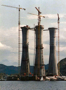
Slip forming, continuous poured, continuously formed, or slipform construction is a construction method in which concrete is poured into a continuously moving form.[1] Slip forming is used for tall structures (such as bridges, towers, buildings, and dams), as well as horizontal structures, such as roadways. Slipforming enables continuous, non-interrupted, cast-in-place "flawless" (i.e. no joints) concrete structures which have superior performance characteristics to piecewise construction using discrete form elements. Slip forming relies on the quick-setting properties of concrete, and requires a balance between quick-setting capacity and workability. Concrete needs to be workable enough to be placed into the form and packed, yet quick-setting enough to emerge from the form with strength. This strength is needed because the freshly set concrete must not only permit the form to "slip" upwards but also support the freshly poured concrete above it.
In vertical slip forming the concrete form may be surrounded by a platform on which workers stand, placing steel reinforcing rods into the concrete and ensuring a smooth pour.[2] Together, the concrete form and working platform are raised by means of hydraulic jacks.[3] Generally, the slipform rises at a rate which permits the concrete to harden by the time it emerges from the bottom of the form.[1]
In horizontal slip forming for pavement and traffic separation walls concrete is laid down, vibrated, worked, and settled in place while the form itself slowly moves ahead. This method was initially devised and utilized in Interstate Highway construction initiated by the Eisenhower administration during the 1950s.
Total station Technology

=== Coordinate measurement ===
Coordinates of an unknown point relative to a known coordinate can be determined using the total station as long as a direct line of sight can be established between the two points. Angles and distances are measured from the total station to points under survey, and the [[coordinate]]s (X, Y, and Z or northing, easting and [[elevation]]) of surveyed points relative to the total station position are calculated using [[trigonometry]] and [[triangulation]].
To determine an absolute location a Total Station requires line of sight observations and must be set up over a known point or with line of sight to 2 or more points with known location.
For this reason, some total stations also have a [[GNSS|Global Navigation Satellite System]] [[computer bus|interface]] which do not require a direct line of sight to determine coordinates. However, GNSS measurements may require longer occupation periods and offer relatively poor accuracy in the vertical axis.
Angle measurement
Most modern total station instruments measure angles by means of electro-optical scanning of extremely precise digital bar-codes etched on rotating glass cylinders or discs within the instrument. The best quality total stations are capable of measuring angles to 0.5 arc-second. Inexpensive "construction grade" total stations can generally measure angles to 5 or 10 arc-seconds.
Distance measurement
Measurement of distance is accomplished with a modulated microwave or infrared carrier signal, generated by a small solid-state emitter within the instrument's optical path, and reflected by a prism reflector or the object under survey. The modulation pattern in the returning signal is read and interpreted by the computer in the total station. The distance is determined by emitting and receiving multiple frequencies, and determining the integer number of wavelengths to the target for each frequency. Most total stations use purpose-built glass corner cube prism reflectors for the EDM signal. A typical total station can measure distances with an accuracy of about 1.5 millimetres (0.0049 ft) + 2 parts per million over a distance of up to 1,500 metres (4,900 ft).[2]
Reflectorless total stations can measure distances to any object that is reasonably light in color, to a few hundred meters
Data processing
Some models include internal electronic data storage to record distance, horizontal angle, and vertical angle measured, while other models are equipped to write these measurements to an external data collector, such as a hand-held computer.
When data is downloaded from a total station onto a computer, application software can be used to compute results and generate a map of the surveyed area. The new generation of total stations (e.g. Hilti POS 15/18) can also show the map on the touch-sceen of the instrument right after measuring the points.
K M V PRASANTH

NAME : K M V PRASANTH
REGD NO : 08QT1A0134
BATCH : 2008-12
MOB NO : 9550299805
E-Mail : bablucivils@gmail.com
Subscribe to:
Posts (Atom)